Injection moulding/process
Process simulation for perfect moulded parts and tools
Minimal development times with constantly high levels of product quality require the increased use of modern simulation procedures. This especially applies to the moulded part and tool design of injection moulding components.
Rheological part and tool design
In this case the filling simulation to optimize the moulded part geometry and the process parameters constitutes an irreplaceable aid. Weak areas such as weld lines or air locks will be recognized and can be removed by changing the gate position, the type of gate or the moulded part geometry even before the tool is being built. In addition to the simulation of single component injection moulding of thermoplastics and thermoplastic elastomers (TPE) the specific characteristics of special injection moulding processes (e.g.: GIT, WIT, 2-Shot, Sandwich) and elastomer or duroplast injection moulding can also be simulated with additional computing options.
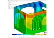
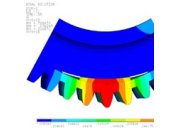
Thermal tool design
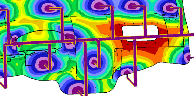
The emerging heat in the cavity must be dissipated as fast as possible during the manufacturing process and a uniform temperature on the surface of the moulded part must be achieved. If this can't be managed, residual stress as well as warpage and sink marks will occur. "Hot spots" in the cavity determine the cycle time. In the past few years the thermal tool design has developed greatly in terms of the precision, effort and economical efficiency. The thermal tool design considerably increases the quality of the components especially in combination with the 3D filling simulation and minimizes the cycle time. Simulation results comprise the optimum cooling performance and also the heating performance in the case of elastomers, the correct location of cooling, necessary tool materials and the optimum use of energy. Areas of nonuniform temperature on the moulded part surface can then be minimized by selective area cooling and by actions such as relocating the cooling position or form following cooling channels, multiple circuit systems and highly heat conductive materials such as Ampcoloy.
Plastics simulation center
The Simulation Centre works on the following tasks amongst others:
- Parameter optimization (e.g. filling behaviour, machine parameters, such as temperature distribution, shear stress distribution, filling pressure, cooling time, holding pressure, clamping force)
- Gating optimization
- Planning of mould provings
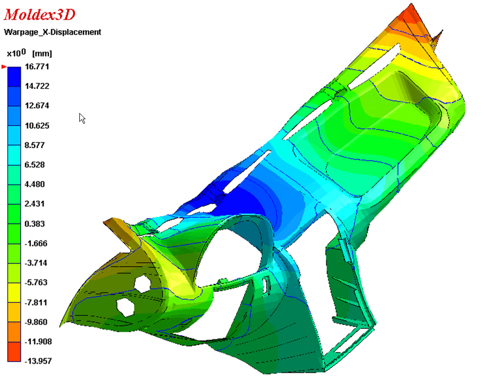
- Warpage calculation and stress analysis
- Fibre orientation and layer analysis
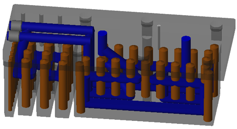
- Thermal analysis and generating cooling geometries: With the volumemetric data based on a 3D design the temperature is calculated in the cavity and in the tool with all the details such as the sliders, ejectors, cooling channels or existing inserts.
- Simulation of form following cooling
- GIT, WIT: Determination of the penetration depth of the fluid, residual wall thickness, optimization of the amount and location of injection needles as well as the level of gas pressure
- 2Shot, Sandwich: Layer distribution
- RIM and elastomer/duromer simulation
Computing software used
We use the programme systems Cadmould and Moldex 3D during the manufacturing simulation.
As a specialist for the simulation of injection moulding processes and component stresses Impetus Plastics Engineering has so far demonstrated its expertise in hundreds of projects. The calculation of component variants, FEM simulations of load conditions, deformation situations and failure modes, structural analyses of glass fibre reinforced injection moulded parts as well as anisotropy tests can be found in the service portfolio.